I-V Measurement System
Introduction
An I-V curve measurement is performed by applying a series of voltages to the device. At each voltage, the current flowing through the device is measured. The supplied voltage is measured by a voltmeter connected in parallel to the device, and the current is measured by an ammeter connected in series. This voltmeter and ammeter can now be integrated to SMU: Source Measure unit, which has been used in this project.
Measurement System GUI
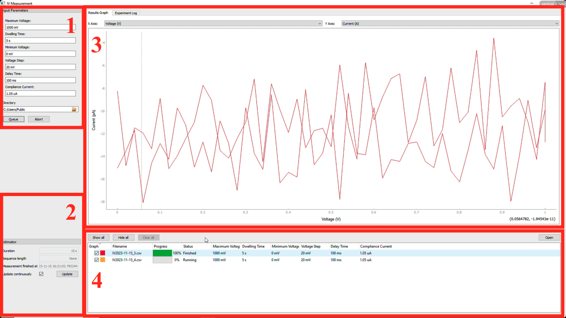
The I-V Measurment system GUI can be shown as below:
It consists of four parts:
- Block 1: Parameter Setting Region: The parameters of the measurement system can be set here, including the Maximum Voltage (mV), Dwelling Time (s), Minimum Voltage (mV), Voltage Step (mV), Delay Time (s) and Compliance Current ($\mu$A).
- Block 2: Experimental Time Estimation Region: The estimated time of the single measurement can be shown here. if a sequencer is used, the estimated time of the whole measurement can be shown here.
- Block 3: Live Plot Region: The live plot of the I-V curve can be shown here. Depending on the needs, the I-R, V-R can also be shown as required.
- Block 4: Experiment Queue Region: The experiment queue can be shown here. The experiment queue can be shown and loaded as required.
I-V Measurement System Sample Video
The I-V Measurement System Sample Video can be shown as below:
I-V Measurmenet System Sample Video
I-V Measurement System Outlook
Additional features can be added to the I-V Measurement System, including:
- Sequencer: The sequencer can be added to the I-V Measurement System, which can be used to perform a series of measurements.
- I-V, V-I switching by toggle button: The I-V, V-I switching can be added to the I-V Measurement System, which can be used to switch the I-V, V-I measurement mode.
- Cyclic Voltammetry: The cyclic voltammetry can be added to the I-V Measurement System, which can be used to perform the cyclic voltammetry measurement.
I-V Measurement System


